2 input nand gate circuit diagram Explain the logic nand gate with its operation and how it works as a Digital logic nand gate(universal gate),its symbols & schematics
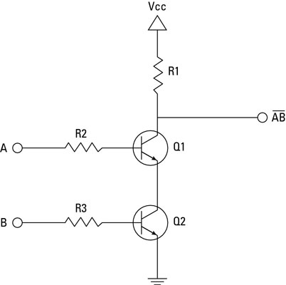
Use Transistors to Build a NAND Gate
Transistor gate
Using transistors as logic gates
A standard digital cmos nand3 gate and its internal transistorNand gate transistor circuit Nand gate using diode circuitUse transistors to build a nand gate.
Nand gate circuit diagram inputs input electronic through pull down explanation working circuits button connected then powerThe transistor nand gate circuit with two input ends Npn transistor nand gate circuitBipolar junction transistor, nand gate, logic, gates, circuit, word.

Nand gate schematic diagram
Nand gate diagramCircuit diagram nand gate Gate nand transistors using wikipedia cmos logic gates diagram schematic electrical wiki fileCircuit diagram of cmos nand gate.
Electrical – current and voltage in cmos logic gate – valuable tech notesNand gate circuit diagram using transistor Nand gate implementation transistors circuit diagram electricalCircuit nand gate input transistor two diagram seekic ends basic ic.

Gate transistor npn nand circuit diagram schematic breadboard sully technologies station pn2222a led
Transistor logic gatesNand gate transistor diagram diagram media Nand gate transistor diode logic using operation circuit explain its universal works electronicspostElectronic – how does the nand gate work using transistors – valuable.
Nand gate circuit diagram and working explanationWhy does the ttl nand gate use a 4 transistor design instead of 2 .